
#L298n driver#
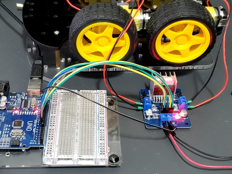
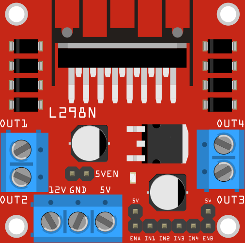
Video describing the work of bridge H - the driver of DC motors. When indictaed low state at the PWM input - free braking (soft stop). When indicated high state at the PWM input - fast braking of the motors (fast stop). The motor rotates at the maximum given speed using PWM (not equal to 0) in a counterclockwise direction. The motor rotates with the maximum given speed using PWM (different from 0) in a clockwise direction. By default, connected to the 5 V by jumper - it means thatthe engine works with maximum speed. PWM signal to control the rotation speed of the motor B. PWM signal to control the rotational speed of the engine A. By default, it is connected to 5 V by jumper -it means that the engine works with the maximum speed. The power of the logical part with the regulator - active after you remove the jumper 5V. The control signals were output into popular goldpin connectors that allows you to combine the system with commissioning plates, for example, with Arduinousing wires.įor Arduino users, available is a sample program simplifying maintenance of the module. Thanks to the screw connectors, ARKpower and engines can be easily connected by fastening the wires using a screwdriver. The module with the popular L298N driver that allows you to control the direction and speed of two DC motors.

#L298n android#
iNode - sensors and modules Bluetooth Android.Components for 3D printers construction.Laser cutting machines - engravers, plotters.Motors speed will be lower if low voltages are on output side.Įxample of L298N module to control motor directionĮnabling pin 6, if we give logic as: Pin5=high, pin7 = low, motor A will start turning clockwise. On input side, 5v is given to the pin 9 (Vss), push buttons and enable bits.On output side,pin 4 (Vs) supplies the motors and it can be upto 46 volts.Here we are not using the current sensing scheme, so we have grounded those pins 1 & 15. This IC is using two different voltages.L298N does not have built in protection diodes we usedexternal diodes to prevent the IC from getting damaged. The output for motor A is obtained from out1 out2 pins and similarly for motor Boutput is obtained from out3 out4 pins. To drive both the motors by using H bridges, both enable bits are set high. While using as a bridge circuit, ENA selects bridge A and ENB selects bridge B. ENA can select two amplifiers A1, A2 and similarly ENB can select two amplifiers B1, B2. Enable bits are used to select specific amplifier.Instead of push button, we can use logic toggle in proteus simulation for our ease.

We can use push buttons and whenever specific push button is pressed, specific motor will start running. INPUTS: Four inputs are provided to the four power amplifiers of L298N.What we want to do is to change the polarity of motors so they can run in either direction depending upon logic. We will use H bridge motor diver IC L298N and two DCmotors. ENB=0v, Low logic (Amplifier B1 and B2 off).ENB=5v, High logic (Amplifier B1 and B2 on).ENA=0v, Low logic (Amplifier A1 and A2 off).ENA=5v, High logic (Amplifier A1 and A2 on).Both enable pins can be used at the same time which makes all for outputs active at the same time.All the four inputs and Enable pins work on 5v TTL logic which makes the connection easy with microcontrollers. Current sense pins can be tied to ground but we can also insert low value resistor and its voltage reading is proportional to current. They can be 1N5819 schottky diodes or 1N4001 rectifier diodes.Įach bridge is provided with enable pins (ENA, ENB) and current sense pins (CSA, CSB). To avoid that voltage spikes there should be some internal parasitic or Flywheel diodes. Pair of H Bridge is used to control a bi-polar stepper motor.īasically L298N is used to drive inductive or magnetic loads, so there can come voltage spikes in output. One H bridge is used to switch the polarity in controlling direction of DC motor. Two of them form H-bridge A while other two form H-bridge B. L298N consists of four independent power amplifiers.


 0 kommentar(er)
